Notes for using Standard Beam Approach
Title
Notes for using Standard Beam Approach
Description
Four pages of notes to help users get the best out of Standard Beam Approach or SBA (the Lorenz System).
Date
1945-08
Temporal Coverage
Coverage
Language
Format
Four pages of duplicated notes
Publisher
Rights
This content is available under a CC BY-NC 4.0 International license (Creative Commons Attribution-NonCommercial 4.0). It has been published ‘as is’ and may contain inaccuracies or culturally inappropriate references that do not necessarily reflect the official policy or position of the University of Lincoln or the International Bomber Command Centre. For more information, visit https://creativecommons.org/licenses/by-nc/4.0/ and https://ibccdigitalarchive.lincoln.ac.uk/omeka/legal.
Identifier
MThirskTP1378816-170214-060001, MThirskTP1378816-170214-060002, MThirskTP1378816-170214-060003, MThirskTP1378816-170214-060004
Transcription
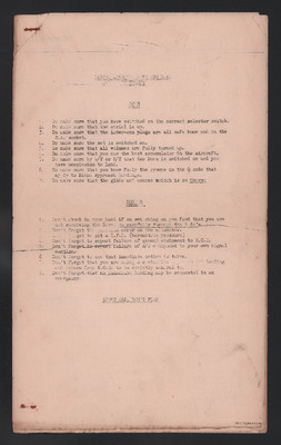
[Underlined] BEFORE ATTEMPTING TO USE B.A. EQUIPMENT [/Underlined]
[Underlined] DO’S [/Underlined]
1. Do make sure that you have switched on the correct selector switch.
2. Do make sure that the aerial is up.
3. Do make sure that the inter-com plugs are all safe home and in the B.A socket.
4. Do make sure the set is switched on.
5. Do make sure that all volumes are fully turned up.
6. Do make sure that you use the best accumulator in the aircraft.
7. Do make sure by W/T or R/T that the Beam is switched on and you have permission to land.
8. Do make sure that you know fully the groups in the Q code that apply to Blind Approach landings.
9. Do make sure that the glide and course switch is on [underlined] Course [/underlined]
[underlined] DON’T’S [/underlined]
1. Don’t chuck in your hand if on switching on you find that you are not receiving the Beam, [underlined] go carefully through the 9 do’s [/underlined]
2. Don’t forget the position error on the altimeter.
3. Don’t forget to get a Q.F.E. (barometric pressure)
4. Don’t forget to report failure of ground equipment to R.C.O.
5. Don’t forget to report failure of A/C equipment to your own signal section.
6. Don’t forget to see that immediate action is taken.
7. Don’t forget that you are doing a controlled approach and landing and orders from R.C.O. to be strictly adhered to.
8. Don’t forget that an immediate landing may be requested in an emergency.
[underlined] ABOVE ALL, DON’T FLAP [/underlined]
[Page Break]
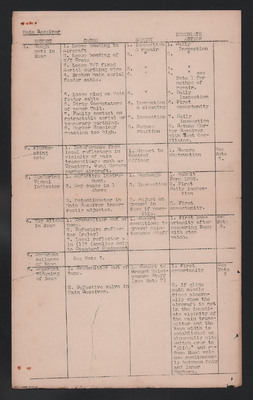
[underlined] Main Receiver [/underlined]
[a] DEFECT [b] CAUSE [c] REMEDY [d] IMMEDIATE ACTION
[a] 1. Rough note in Beam [b] 1. Loose bonding in Aircraft 2. Loose bonding of W/T Crate 3. Loose W/T fixed Aerial earthing wire 4. Broken main aerial feeder cable. 5. Loose plug on Main feeder cable 6. Dirty Commutators of power Unit. 7. Faulty contact on retractable aerial or temporary earthing. 8. Marker Receiver reaction too high. [c] 1. Inspection & repair 2. Inspection & repair 3. Inspection & repair 4. Inspection & repair 5. Inspection & repair. 6. Inspection & cleaning 7. Inspection 8. Reduce reaction. [d] 1. Daily Inspection 2. Daily Inspection 3. Daily Inspection 4. Daily Inspection see Note 1 for method of repair. 5. Daily Inspection 6. First opportunity 7. Daily Inspection 8. Retune Marker Receiver with Test Oscillator.
[a] 2.Fluctuating note [b] 1. Interference from local reflectors in vicinity of main transmitters such as Tractors, Gang Mowers parked aircraft. [c] 1. Report to Control Officer [d] 1/ Remove obstruction [e] See Note 3.
[a] 3. Wandering Visual Indicator [b] 1. Defective instrument. 2. Any cause in 1 above 3. Potentiometer in Main Receiver incorrectly adjusted. [c] 1. Exchange 2. Inspection 3. Adjust on ground in Beam if possible. [c] 1. Submit Form 1022. 2. First Daily Inspection 3. First opportunity.
[a] 4. Key clicks in Beam [b] 1. Transmitter out of tune. 2. Defective reflector (relay) 3. Local reflector a in (1) 6 (applies only to Standard Equipment [c] 1. Report conditions to ground maintenance staff [d] 1. First opportunity after measuring Beam with stop watch [e] See Note 3.
[a] 4.[sic] Apparent collapse of Beam [b] See Note 3.
[a] 5. Apparent widening of Beam [b] 1. Transmitter out of tune. 2. Defective valve in Main Receiver. [c] Report to Ground Maintenance Staff (see Note 2) [d] 1. First opportunity 2. If glide path needle rises abnormally when the aircraft is not in the immediate vicinity of the main transmitter and the Bean width is established as abnormally wide switch over to “glide” and reduce Hand volume continuously between Outer and Inner Markers. [e] See Note 3
[Page Beak]
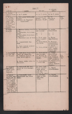
[underlined] Page II [/underlined]
[a] DEFECT [b] CAUSE [c] REMEDY [d] IMMEDIATE ACTION
[a] 6. Badly defined Beam edges. [b[ as in 5 above [c] As in 5 above [d] As in 5 above
[a] 7. Dashes not clear, producing sound like “perlonk” & “dots” apparently longer than normal. [b] 1. Defective reflector relays (Applies to Standard Equipment) [c] 1. Report to Ground Maintenance Staff [d] 1. No Receiver action [e] See Note 3
[a] 8. Weak Signal [b] 1. Broken aerial Feeder Cable 2. Defective telephone jacks 3. Defective telephone earpieces 4. Receiver out of tune 5. Accumulator run down 6. Main aerial retracted or earthed. [c] 1. Inspection and repair 2. Inspection and repair 3. Inspection and repair 4. Test with test oscillator. 5. Inspection and test. 6. Inspection [d] 1. daily inspection 2. daily inspection 3. daily inspection 4. First opportunity 5. Replace Accumulator immediately 6. Erect earial [sic], remove earth, first opportunity.
[a] 9. Temporary cut out of Signals [b] 1. Defective telephone jacks in aircraft. 2. Partial failure of Main transmitter. 3. Loose valve pins in Receiver. [c] Inspection and repair. 2. Report to Ground M’ance Staff. 3. Inspection & open out. [d] 1. Daily Inspection 2. Ascertain whether such a failure occurred. 3. First opportunity after failure occurs. [e] See Note 3.
[a] 10. Fading out after short periods of running. [b] 1. Receiver off tune owing to temperature rise. [c]. 1. Tune with Test oscillator after set has been run for about 30 mins. [d] 1. First opportunity.
[a] 11. After passing thro’ “Cone of silence” signals taken abnormally long period in returning: accompanied by periods of “Cutout” when away from the Main Beacon. [b] 1. Defective Neon Stabilizer in Power Unit. [c] Replace with a serviceable Neon. [d] 1. First opportunity.
[Page Break]
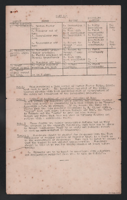
[underlined] PAGE III [/underlined]
[a] DEFECT [b] CAUSE [c] REMEDY [d] IMMEDIATE ACTION
[a] [underlined] MARKER RECEIVER [/underlined] 1. No Signals [b] 1. Broken feeder cable. 2. Receiver out of tune 3. Accumulator run down 4. Transmitter off tune [c] 1. Inspection & repair. 2. Test with test oscillator 3. Inspection & test 4. Report to Ground M’ance staff. [d] 1. Daily Inspection 2. First opportunity 3. Replace accumulator immediately 4. First opportunity [e] See Note 1. See Note 3
[a] 2. Signals not audible above 1000’ [b] 1. Defective transmitter crystals. 2 Faulty coupling of Di-pole transformer 3. Receiver off tune [c] Report to Ground M’ance staff. 2. Test with test oscillator 3. Test with test oscillator [d] 1. First opportunity 2. First opportunity 3. First opportunity
[a] 3. Gruff Marker signal [b] 1. Marker receiver reaction too high [c] Reduce reaction [d] 1. First opportunity
[a] 4. Marker signal spread too long. [b] As in 3 above
[underlined] Note 1. [sic] [/underlined] When repairing a Main Aerial or Marker Feeder Cable, little heat must used. The Insulating material of the cable becomes plastic with heat involving risk of distribution of the cable and impairment of the insulating properties.
[underlined] Note 2 [/underlined] [underlined] Methos of testing of apparent widening of Beam [/underlined]
Do not switch off Receivers after landing but observe whether glide path needle is abnormally high when switch is on “Course” i.e with A.V.C. in circuit. If so, remove the three 9D 2 valves from the Main receiver (positions 1, 3, 4), and with a “megger” test each valve between Cathode and Grid, the “Line” to Cathode and the “earth” to grid and vice versa.
Reject any valve that does not show an Infinity Reading and replace with a serviceable valve.
[underlined] Note 3 [/underlined] These faults are mainly transmitter defects but as they are apparent in the Aircraft Receivers, much help can be given to Ground Maintenance Staff by an oraly [sic] and reliable report as soon as such a defect is noticeable.
[underlined] Tuning 1 [/underlined] Receivers should be checked for frequency with the Test Oscillator at regular periods or whenever there is a doubt as to the correctness of frequency. Care must be taken to ensure that the tuning is not altered unnecessarily. Receivers should be allowed to run for thirty minutes at least before tuning.
2. Circuits are to be tuned in accordance with selectors and frequencies published from time to time in C.C.O.’s.
Collection
Citation
“Notes for using Standard Beam Approach,” IBCC Digital Archive, accessed December 8, 2024, https://ibccdigitalarchive.lincoln.ac.uk/omeka/collections/document/39670.
Item Relations
This item has no relations.