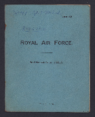
John Hitchcock's Rigging Notes

MHitchcockJS740899-170926-24.pdf

Title

John Hitchcock's Rigging Notes

Description

Notes kept by John during his training.

Creator

Coverage

Language

Format

One booklet

Rights

This content is available under a CC BY-NC 4.0 International license (Creative Commons Attribution-NonCommercial 4.0). It has been published ‘as is’ and may contain inaccuracies or culturally inappropriate references that do not necessarily reflect the official policy or position of the University of Lincoln or the International Bomber Command Centre. For more information, visit https://creativecommons.org/licenses/by-nc/4.0/ and https://ibccdigitalarchive.lincoln.ac.uk/omeka/legal.

Contributor

Identifier

MHitchcockJS740899-170926-24

Transcription

740899 Sgt. J. Hitchcock

Form 619.

[underlined] RIGGING [/underlined]

ROYAL AIR FORCE

Small Notebook for use in Schools.

[page break]

[blank page]

[page break]

Advantages of Metal over Other Forms.

[circled 1] Wider choice of material possessing requisite properties.
[circled 2] Provides rigid structure but is relatively durable.
[circled 3] Parts can be made to fine limits.
x [circled 4] All attachments are metal to metal [symbol] definite.
[circled 5] Accurate interchangeability of parts as materials lend themselves to precise measurement & consistent reproduction.
[circled 6] For all structural purposes, the metals used on aircraft are practically unaffected by changes of climatic condition, but are subject to surface oxidation & other forms of corrosion unless care is taken for their preservation.

[underlined] Disadvantages [/underlined]

[circled 1] Corrosion
[circled 2] Vibration.

Vibration cut down by mounting certain components on rubber (tanks, engine etc).
Corrosion can be
[circled a] Surface
[circled b] Inter chrystalline [sic]

[page break]

Corrosion red (rust) on ferrous metals. On light alloys white powder, verdigris on copper alloys.

Caused by great humidity (especially on sea air)
Inter-crys. may be due to same causes as surface. More noticeable when some kind of inter-action is present; & owing to surface contract between different types of metal. The inter-action is electrolytic, i.e. a minute difference of electrical potential is set up between parts.

[underlined] Pilting [/underlined] is an impurity [deleted] expos [/deleted] in metal exposed by manufacture [deleted word] to the surface & causing corrosion entering deeply below surface.

No abrasive to take off surface corrosion, but a paraffin rag.

[underlined] Prevention of Corrosion [/underlined]

[circled 1] Painting the surface.
[circled 2] Stove enamel
[circled 3] Electrically deposit a metal (e.g. nickel, zinc) on surface.
[circled 4] For ferrous metals, adding certain elements (chromium)
[circled 5] For light alloys, giving anodic treatment which brings to surface aluminum hydroxide in a glassy adherent form.

[page break]

[underlined] Fuselages [/underlined]

3 Types.
1. Wooden
2. All metal
3. Composite.

3 diff. types of consideration for 1st two
[circled a] Braced girder
[circled b] Mono-coque
[circled c] Semi-mono-coque

Also Geodetic (all metal only).

Usually metal front, wooden rear of braced girder construction for the Composite.

[underlined] Braced girder [/underlined]
[underlined] Ordinary type [/underlined]
[diagram]

[underlined] N Type [/underlined]
[diagram]

[page break]

[underlined] Warren type [/underlined]

[diagram]
In all-welded fuselage no bracing wires.

[underlined] Geodetic [/underlined]
4 main longerons, no upright struts. Main advantage is that can’t be twisted.

[underlined] Mono-coque [/underlined]
Consists of formers & stringers (true). [diagram]
All wood. No internal bracing.

Panel bracing (semi-monocoque).
4 longerons, upright struts. Each side built separately in a jig. Also diagonals where necessary. Cover with a sheet of 3 ply. Bulkheads or formers at 3 places in fuselage. Covered with fabric.

[diagram]

[page break]

[underlined] Semi-mono-coq. metal [/underlined]
[circled 1] Formers & stringers in same manner as true m-c. fuselage with sheet metal riveted to them in form of large panels.
[circled 2] Formers only (bulkheads)

[diagrams]

[underlined] Main Planes [/underlined]

[circled 1] [underlined] Spars. [/underlined] Main members & take all stresses of normal & aerobatic flight, transferring them evenly to fuselage.
[circled 2] [underlined] Drag Struts & Bracings. [/underlined] These are fitted to brace spars into semi-rigid structure & to help transfer forces throughout plane.
[circled 3] [underlined] Drag bracing wires [/underlined] prevent [deleted] any [/undeleted] planes from folding backwards
[circled 4] [underlined] Anti-drag wires [/underlined] take forces in opposite direction
[circled 5] [underlined] Compression Rib [/underlined] Act in same way as strut but also act as a rib. Usually fitted at strut joints where extra strength is required to minimise twist of spars.
[circled 6] [underlined] Camber on Main Rib [/underlined] Fitted to give & maintain to

[page break]

the plane its aerofoil section. When plane is covered with fabric it is secured to these ribs.
[circled 7] [underlined] Nose ribs on riblets [/underlined] Absorb extra forces encountered during flight. As front of plane (leading edge to front spar) take initial shock of airflow.
[circled 8] [underlined] Leading & trailing edges [/underlined] Anchorages & steadying tubes for nose & main ribs forming boundary lines of the aerofoil completing its shape.
[circled 9] [underlined] Wing Tip [/underlined] Usually curved & of larger diameter than leading & trailing edge as unsupported [deleted] by [/deleted] & takes extra pull of fabric on end of plane also to suit manhandling on ground.
[circled 10] [underlined] Root Rib [/underlined] Of same aerofoil section as main rib but strengthened to take extra forces of end pull of fabric.
[circled 11] [underlined] Dope Struts [/underlined] Fixed to root ribs etc as support against pull on thrust.
[circled 12] [underlined] Torque Tubes [/underlined] Eliminate effect of torque on aileron by pull of control lever.

[underlined] Spars [/underlined]
[circled 1] Solid drawn tube [diagram]
[circled 2] Built [inserted] up [/inserted] of strip metal (steel)
[circled 3] Extruded section (light alloy).

[page break]

[underlined] Pierced Rivet [/underlined] [circled 1] [diagram]

[circled 2] [underlined] Shobert [/underlined] [diagram]

[underlined] Oleo Legs. [/underlined]
Recuperation Cylinder (inside is brake [indecipherable word]).
Bottom half is piston & piston head.
Oil level valve. Filling valve.
Air pressure varies according to aircraft.

[underlined] Aerofoils [/underlined]

[diagram]

[underlined] Group [circled I] [/underlined] [inserted] High Camber [/inserted] High Lift (bad speed properties).

Group [circled II] Low Camber (low lift, high speed).

Group [circled III] General Purpose (compromise of [circled I] & [circled II].

[page break]

[underlined] Flaps [/underlined]
[circled 1] Camber flaps. Reduced take off run, steeper climb, steeper glide. moved trailing edge.

Plain landing flap (camber flap)

[diagram] (21°)

[circled 2] [diagram] (60°) Split flap

[circled 3] [diagram] (90°) Nap flap.

[circled 4] [diagram] (45°) Handley Page
Slotted Flap

[circled 5] diagram (40°) Fowler flap
(increases wing area)

[page break]

[blank page]

Citation

John Hitchcock, “John Hitchcock's Rigging Notes,” IBCC Digital Archive, accessed December 8, 2024, https://ibccdigitalarchive.lincoln.ac.uk/omeka/collections/document/36990.

Item Relations

This item has no relations.