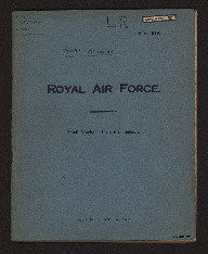
RAF Notebook
Title
RAF Notebook
Description
Notes on pyrotechnics, bombing ballistics, bomb aiming, bombs, armament (guns), bombing errors,
Creator
Language
Format
Multi-page notebook with handwritten notes and diagrams
Publisher
Rights
This content is available under a CC BY-NC 4.0 International license (Creative Commons Attribution-NonCommercial 4.0). It has been published ‘as is’ and may contain inaccuracies or culturally inappropriate references that do not necessarily reflect the official policy or position of the University of Lincoln or the International Bomber Command Centre. For more information, visit https://creativecommons.org/licenses/by-nc/4.0/ and https://ibccdigitalarchive.lincoln.ac.uk/omeka/legal.
Contributor
Identifier
MRosserLV745193-190517-33
Transcription
R.A.F. GRANTHAM. [underlined] LINCS. [/inderlined]
L R ARMAMENT [symbol]
Form 619.
[underlined] 745193 SGT. ROSSER [underlined]
ROYAL AIR FORCE.
Small Notebook for use in Schools.
91/6358. Wt.7069. 700M. 10/39. P. & T.
[page break]
[symbol]
[page break]
L R ARMAMENT [symbol]
Pyrotechnics.
Used in R.A.F. for signalling & illumination.
Regulations regarding aircraft storage when fitted with flares [symbol] Chapt. 12 Sect. 8 Par. 775. - K.R’s
[page break]
[blank page]
[page break]
[underlined] ARMAMENT [/underlined]
[underlined] Bombing from Moving A/c in still air. [/underlined]
[drawing]
v = ft for sea.
O. = [indecipherable word] bomb released
H. = Height.
G = Ground level.
X = [indecipherable word] bomb hits ground.
A = Bombing angle.
Gravity Acceleration 32 ft per sec.
[calculations]
[underlined] Bomb falling from 1600’ taken 10 secs in still air [/underlined]
[page break]
[underlined] Bomb dropped from aircraft accounting for W/V. [/underlined]
[drawing]
[page break]
[underlined] Finding W/V. with Bomb sight. [/underlined]
[underlined] 3 Course Method [/underlined]
A./ 1. Set Computed A/S. x maximum wind speed.
2. Level sight
3. On any straight and level course eliminate drift.
B./ 2. Unclamp.
Put red on red. Reclamp . Down rule and draw line
C./ Turn through 060⁰. Eliminate drift. Unclamp. Put red on red, Reclamp, Down rule & draw line
D./ Turn through 060⁰ (or back 120⁰). Eliminate drift Unclamp. Put red on red. Reclamp, Down rule & draw line.
E./ Unclamp. Place centre of ‘cocked hat’ over wind arrow. [underlined] Reclamp. [/underlined]
This sets wind direction
F./ Place wind speed bar at right angle to A/S bar. Adjust on wind screw until mole in cursor is over the centre of cocked hat (this may necessitate moving cursor). Wind speed is now set.
[page break]
[underlined] Finding W/V. with Bomb Sight. [/underlined]
[underlined] Timing lead Method. [/underlined]
1./ Set terminal velocity to infinity.
Maximum Wind Speed.
Computed Air Speed
Set height on red and side scale to computed and corrected height above earth’s surface.
2./ Level sight
3./ On any straight, level and steady course eliminate drift.
4./ Sighting through backsight time passage of object on ground between consecutive sets of bends [symbol]. Repeat this 3 times and use mean reading
5./ Unclamp. Without altering drift angle set red on red. Reclamp.
6./ Lower wind guage [sic] bar. Adjust cursor until true Air Speed on cursor cuts “time in seconds” curve found in four.
7./ Mark wind point on bearing plate through hole in [symbol] cursor
8./ Unclamp. Set wind point over tail of wind arrow. Reclamp. Wind direction is now set
9./ Set wind speed bar at right angles to Air Speed bar. Adjust wind speed bar control until hole in cursor covers wind point (this may necessitate moving cursor).
10./ Bomb aimer should check wind found by keeping red on red and again timing passage of objects between bends as in ‘4’ Provided original course has been maintained, time found will agree with previous determination and also with “minutes to travel 60” reading on the ground speed scale
[page break]
of course has not been maintained with red on red objects should travel down drift wires and timing should agree with minutes to travel 60” on ground speed scale, if this is not so an incorrect wind has been found. N.B. Before bombing. Appropriate T.V. for bombs used must be set and height slider set to true height on bombing scale.
[underlined] BOMBS [/underlined]
T.N.T. ( Tri-Nitro-Tolene)
Amotol (T.N.T. + Ammonium Nitrate)
Baratol (T.N.T + Barium. Nitrate]
[underlined] “B” bomb [/underlined] – use only for sea work
[drawing]
[underlined] General. Purpose Bomb [underlined] – fuse either in tail or nose. High Explosive Content – high blast – robust case – fair penetration – high fragmentation.
[underlined] S.A.P. – Semi Armour Piercing [/underlined] – fuse in tail to allow for penetration Good Penetration – high blast – medium fragmentation.
[underlined] A.P. – Armour Piercing. [/underlined] – fuse in tail High penetration – high blast – low fragmentation
[underlined] A.S. – Anti-Submarine [/underlined] – fuse in nose – delayed – but should bomb hit object it will explode on impact owing to crumpling of fuse. Great blast effect – penetration.
[page break]
[underlined] Vickers G.O. [/underlined]
[underlined] Parts & their functions. [/underlined]
Piston Stops – Form a stop for piston at end of forward movement.
Magazine Catches, front & rear – Retain magazine.
Barrel Strap – Locks barrel to body.
Cocking handle, slide & catch – Holds cocking handle in forward position when gun is fired.
Cocking handle slide – Governs movement of cocking handle
Cocking handle lug – Engages in ‘cocking handle lug slot’ and draws” piston to rear.
Buffer Spring – takes shock of recoil and assists in forward movement.
Trigger rod stop – Controls [deleted] sear from [/deleted] movement of sear catch.
Sear buffer plunger – [deleted] Takes m [/deleted] Connection between sear buffer spring and sear lever.
Sear buffer Spring – Repositions sear through medium of plunger and sear lever – conveys movement.
Sear Catch – In event of trigger being eased prevents sear from rising.
Sear Stop - Ensures that sear rises to its fullest extent.
Firing pin spring – Withdraws firing pin and prevents firing pin from going forward until struck hammer.
Horizontal Surface – A safety device on the backward & forward movement.
[page break]
Locking Cam – Locks the breach block
Ejector Cam – Controls movement of ejector
Feed Piece – Forces round from lip of magazine into chamber
Bullet lead – Guides bullet into chamber and forces rim of cartridge behind extractor
Platform – Supports last round in correct position in lips of magazine and prevents overloading.
[underlined] Trigger Mechanism. [/underlined]
[underlined] The release of the sear. [/underlined]
When the trigger is pressed the short arm forces the trigger rod forward and so compresses the trigger rod spring. The forked forward end of the trigger rod rotates sear on its axis pin, compressing the sear spring and with drawing [sic] the nose of the sear from the piston bent. Meanwhile the head of the sear catch is forced forward by the sear catch spring until its two upper arms have engaged over the step on the sear thus preventing the sear from rising until trigger has been fully released. As the breach block moves forward, the feed piece engages against the base of the cartridge held in the lip of the magazine forcing the bullet end of the cartridge under the front of the bullet guide guiding the bullet into the chamber
[underlined] Engagement of the sear [/underlined]
When the trigger is released the trigger and trigger
[page break]
rod are forced back to their normal positions by the trigger rod spring thus freeing the forked end of the trigger rod from the lower arm of the sear. The sear however is still unable to rise until the trigger rod has almost reached the limit of its backward movement, when the trigger rod stops on the trigger rod bear against the [deleted] trigger rod [/deleted] [inserted] rear catch [/inserted] and rotate it to the rear, [deleted] and rotate it to the rear [/deleted] disengaging the two upper arms of catch from stop on rear of sear. The sear is now forced up into its normal position by the spring. The shock of the impact between the sear and the piston bent is [deleted word] absorbed by the sear buffer spring through the medium of sear buffer and sear lever.
[underlined] Vickers G.O [/underlined]
[underlined] To load Magazine [/underlined] – To load & prepare mag. (hand filling)
a) Withdraw retaining pin & remove driver
b) Rotate top plate until follower is visible against the cartridge bullet guide.
c) Slide first cartridge base first, into the lips. Keeping the cartridge as parallel to the bottom plate as possible.
d) Turn top plate until next [indecipherable word] appears & repeat with remaining cartridges as for “c”, until no further rotation of bottom plate is possible.
e) Insert driver and turn anti-clockwise to engage spring anchorage.
f) Place magazine on winding plate and with winding handle turn driver [ deleted words] maximum tension and insert retaining pin.
[page break]
[underlined] Height & A/S Computer. [/underlined]
Indicated & Computed A/S. coincide when temp is set at +15⁰
Indicated & Computed Height coincide when temp is set at +10⁰
Ground Pres – 1000 mbr } Computed A/S 120 mph. Computed Ht. 9,200 ft. [symbol]
Temp. -20⁰ } Computed A/S 120 mph. Computed Ht. 9,200 ft. [symbol]
Ind. Ht. 10,000 ft. } Computed A/S 120 mph. Computed Ht. 9,200 ft. [symbol]
Ind. A/S. 150 mph. } Computed A/S 120 mph. Computed Ht. 9,200 ft. [symbol]
Ground Pres 990 } Computed A/S 223 mph. Computed Ht. 6,000 ft. [symbol]
Temp +5⁰ } Computed A/S 223 mph. Computed Ht. 6,000 ft. [symbol]
Ind. Ht. 6000 ft } Computed A/S 223 mph. Computed Ht. 6,000 ft. [symbol]
Ind A/S. 200 mph } Computed A/S 223 mph. Computed Ht. 6,000 ft. [symbol]
G.P. 1013 } Computed A/S 169 mph. Computed Ht. 2,300 [symbol]
Temp -15 } Computed A/S 169 mph. Computed Ht. 2,300 [symbol]
Ind. Ht. 2500 } Computed A/S 169 mph. Computed Ht. 2,300 [symbol]
A/S 170 } Computed A/S 169 mph. Computed Ht. 2,300 [symbol]
G.P. 998 } Computed A/S [deleted] 163 1/2 [/deleted] [inserted] 167 [/inserted] mph. Computed Ht. 14,400 ft. [symbol]
Temp +7⁰ } Computed A/S [deleted] 163 1/2 [/deleted] [inserted] 167 [/inserted] mph. Computed Ht. 14,400 ft. [symbol]
Ind. Ht. 14000 ft } Computed A/S [deleted] 163 1/2 [/deleted] [inserted] 167 [/inserted] mph. Computed Ht. 14,400 ft. [symbol]
A/S 130 } Computed A/S [deleted] 163 1/2 [/deleted] [inserted] 167 [/inserted] mph. Computed Ht. 14,400 ft. [symbol]
[page break]
[underlined] Vickers G.O [/underlined]
a. Place magazine on winding plate.
b. With winding handle assembled, remove [deleted] winding [/deleted] retaining pin and ease off all tension
c. Remove driver and top plate and empty live rounds from magazine body and assemble magazine.
[underlined] Safety Devices [/underlined]
1. [underlined] Manual. [/underlined] – Safety catch. Note – The action of applying safety catch does not prevent gun being cocked.
2. [underlined] Closing of breach. [/underlined] The horizontal surface at rear of piston rod in conjunction with locking cam ensure that breach block is closed.
3. [underlined] Horizontal Surface [/underlined] Ensures that breach block is locked before pin can be fired.
4. [underlined] Opening of the breach. [/underlined] Horizontal surface ensures that breach is locked on backward movement of piston rod until bullet and bulk of gases have escaped.
5. [underlined] Gas escape hole in breach block. [/underlined]
6. [underlined] Firing pin spring. [/underlined] Holds the firing pin to the rear.
[page break]
[underlined] Vickers G.O. [/underlined]
1./ Explain reason for slight delay in opening breach after rounds have fired.
2./ Explain reason for gun being fitted with floating firing pin.
3./ Function of the sear catch spring? 4./ Function of the sear buffer spring?
1./ After a round has been fired the gases travel round the gas plug & gas cylinder until they come into contact with the piston which is forced back by same. Any excess pressure of the gases is allowed to escape through the hole in the gas cylinder. The piston actually travels back 3/10” before the piston slide connects with the breach block and so forcing the breach block down.
2./
[underlined] To load Vickers G.O. [/underlined]
1. Put Safety Catch to ‘Safe.
2. Pull back cocking handle to cock gun.
3. Return cocking handle to forward position
4. Place magazine rear catch first – in position on the breach [indecipherable word] & [deleted] 5. [/deleted] give upward pull to ensure security.
5. Set safety catch to fire.
[underlined] To Unload. [/underlined]
1. With the palm of the hand, press forward the rear catch flap and with the fingers of same hand grasp leather handle, lifting magazine rear catch first from gun.
2. If breach block is held to the rear – press trigger & push cocking lever forward.
3. If breach block is in forward position – pull back cocking handle and return to forward position then press trigger.
[page break]
[underlined] Bombing Errors [/underlined]
[diagram]
If A/S is overset bombs will fall short. [indecipherable word] A/S to correct.
If 7/[indecipherable letter] is overset bombs will fall [indecipherable word] of target
If Ht. is overset bombs overshoots along track
If B/S tilted forward bombs [two deleted word] overshoots along track.
If B/S installed to right bombs falls to left of target right angle to track.
If W/S overset bombs falls upwind of target
If W/D set in excess bomb falls at right angles to wind
If B/S tilted to right bomb falls to right target.
[page break]
[blank page]
[page break]
[blank page]
L R ARMAMENT [symbol]
Form 619.
[underlined] 745193 SGT. ROSSER [underlined]
ROYAL AIR FORCE.
Small Notebook for use in Schools.
91/6358. Wt.7069. 700M. 10/39. P. & T.
[page break]
[symbol]
[page break]
L R ARMAMENT [symbol]
Pyrotechnics.
Used in R.A.F. for signalling & illumination.
Regulations regarding aircraft storage when fitted with flares [symbol] Chapt. 12 Sect. 8 Par. 775. - K.R’s
[page break]
[blank page]
[page break]
[underlined] ARMAMENT [/underlined]
[underlined] Bombing from Moving A/c in still air. [/underlined]
[drawing]
v = ft for sea.
O. = [indecipherable word] bomb released
H. = Height.
G = Ground level.
X = [indecipherable word] bomb hits ground.
A = Bombing angle.
Gravity Acceleration 32 ft per sec.
[calculations]
[underlined] Bomb falling from 1600’ taken 10 secs in still air [/underlined]
[page break]
[underlined] Bomb dropped from aircraft accounting for W/V. [/underlined]
[drawing]
[page break]
[underlined] Finding W/V. with Bomb sight. [/underlined]
[underlined] 3 Course Method [/underlined]
A./ 1. Set Computed A/S. x maximum wind speed.
2. Level sight
3. On any straight and level course eliminate drift.
B./ 2. Unclamp.
Put red on red. Reclamp . Down rule and draw line
C./ Turn through 060⁰. Eliminate drift. Unclamp. Put red on red, Reclamp, Down rule & draw line
D./ Turn through 060⁰ (or back 120⁰). Eliminate drift Unclamp. Put red on red. Reclamp, Down rule & draw line.
E./ Unclamp. Place centre of ‘cocked hat’ over wind arrow. [underlined] Reclamp. [/underlined]
This sets wind direction
F./ Place wind speed bar at right angle to A/S bar. Adjust on wind screw until mole in cursor is over the centre of cocked hat (this may necessitate moving cursor). Wind speed is now set.
[page break]
[underlined] Finding W/V. with Bomb Sight. [/underlined]
[underlined] Timing lead Method. [/underlined]
1./ Set terminal velocity to infinity.
Maximum Wind Speed.
Computed Air Speed
Set height on red and side scale to computed and corrected height above earth’s surface.
2./ Level sight
3./ On any straight, level and steady course eliminate drift.
4./ Sighting through backsight time passage of object on ground between consecutive sets of bends [symbol]. Repeat this 3 times and use mean reading
5./ Unclamp. Without altering drift angle set red on red. Reclamp.
6./ Lower wind guage [sic] bar. Adjust cursor until true Air Speed on cursor cuts “time in seconds” curve found in four.
7./ Mark wind point on bearing plate through hole in [symbol] cursor
8./ Unclamp. Set wind point over tail of wind arrow. Reclamp. Wind direction is now set
9./ Set wind speed bar at right angles to Air Speed bar. Adjust wind speed bar control until hole in cursor covers wind point (this may necessitate moving cursor).
10./ Bomb aimer should check wind found by keeping red on red and again timing passage of objects between bends as in ‘4’ Provided original course has been maintained, time found will agree with previous determination and also with “minutes to travel 60” reading on the ground speed scale
[page break]
of course has not been maintained with red on red objects should travel down drift wires and timing should agree with minutes to travel 60” on ground speed scale, if this is not so an incorrect wind has been found. N.B. Before bombing. Appropriate T.V. for bombs used must be set and height slider set to true height on bombing scale.
[underlined] BOMBS [/underlined]
T.N.T. ( Tri-Nitro-Tolene)
Amotol (T.N.T. + Ammonium Nitrate)
Baratol (T.N.T + Barium. Nitrate]
[underlined] “B” bomb [/underlined] – use only for sea work
[drawing]
[underlined] General. Purpose Bomb [underlined] – fuse either in tail or nose. High Explosive Content – high blast – robust case – fair penetration – high fragmentation.
[underlined] S.A.P. – Semi Armour Piercing [/underlined] – fuse in tail to allow for penetration Good Penetration – high blast – medium fragmentation.
[underlined] A.P. – Armour Piercing. [/underlined] – fuse in tail High penetration – high blast – low fragmentation
[underlined] A.S. – Anti-Submarine [/underlined] – fuse in nose – delayed – but should bomb hit object it will explode on impact owing to crumpling of fuse. Great blast effect – penetration.
[page break]
[underlined] Vickers G.O. [/underlined]
[underlined] Parts & their functions. [/underlined]
Piston Stops – Form a stop for piston at end of forward movement.
Magazine Catches, front & rear – Retain magazine.
Barrel Strap – Locks barrel to body.
Cocking handle, slide & catch – Holds cocking handle in forward position when gun is fired.
Cocking handle slide – Governs movement of cocking handle
Cocking handle lug – Engages in ‘cocking handle lug slot’ and draws” piston to rear.
Buffer Spring – takes shock of recoil and assists in forward movement.
Trigger rod stop – Controls [deleted] sear from [/deleted] movement of sear catch.
Sear buffer plunger – [deleted] Takes m [/deleted] Connection between sear buffer spring and sear lever.
Sear buffer Spring – Repositions sear through medium of plunger and sear lever – conveys movement.
Sear Catch – In event of trigger being eased prevents sear from rising.
Sear Stop - Ensures that sear rises to its fullest extent.
Firing pin spring – Withdraws firing pin and prevents firing pin from going forward until struck hammer.
Horizontal Surface – A safety device on the backward & forward movement.
[page break]
Locking Cam – Locks the breach block
Ejector Cam – Controls movement of ejector
Feed Piece – Forces round from lip of magazine into chamber
Bullet lead – Guides bullet into chamber and forces rim of cartridge behind extractor
Platform – Supports last round in correct position in lips of magazine and prevents overloading.
[underlined] Trigger Mechanism. [/underlined]
[underlined] The release of the sear. [/underlined]
When the trigger is pressed the short arm forces the trigger rod forward and so compresses the trigger rod spring. The forked forward end of the trigger rod rotates sear on its axis pin, compressing the sear spring and with drawing [sic] the nose of the sear from the piston bent. Meanwhile the head of the sear catch is forced forward by the sear catch spring until its two upper arms have engaged over the step on the sear thus preventing the sear from rising until trigger has been fully released. As the breach block moves forward, the feed piece engages against the base of the cartridge held in the lip of the magazine forcing the bullet end of the cartridge under the front of the bullet guide guiding the bullet into the chamber
[underlined] Engagement of the sear [/underlined]
When the trigger is released the trigger and trigger
[page break]
rod are forced back to their normal positions by the trigger rod spring thus freeing the forked end of the trigger rod from the lower arm of the sear. The sear however is still unable to rise until the trigger rod has almost reached the limit of its backward movement, when the trigger rod stops on the trigger rod bear against the [deleted] trigger rod [/deleted] [inserted] rear catch [/inserted] and rotate it to the rear, [deleted] and rotate it to the rear [/deleted] disengaging the two upper arms of catch from stop on rear of sear. The sear is now forced up into its normal position by the spring. The shock of the impact between the sear and the piston bent is [deleted word] absorbed by the sear buffer spring through the medium of sear buffer and sear lever.
[underlined] Vickers G.O [/underlined]
[underlined] To load Magazine [/underlined] – To load & prepare mag. (hand filling)
a) Withdraw retaining pin & remove driver
b) Rotate top plate until follower is visible against the cartridge bullet guide.
c) Slide first cartridge base first, into the lips. Keeping the cartridge as parallel to the bottom plate as possible.
d) Turn top plate until next [indecipherable word] appears & repeat with remaining cartridges as for “c”, until no further rotation of bottom plate is possible.
e) Insert driver and turn anti-clockwise to engage spring anchorage.
f) Place magazine on winding plate and with winding handle turn driver [ deleted words] maximum tension and insert retaining pin.
[page break]
[underlined] Height & A/S Computer. [/underlined]
Indicated & Computed A/S. coincide when temp is set at +15⁰
Indicated & Computed Height coincide when temp is set at +10⁰
Ground Pres – 1000 mbr } Computed A/S 120 mph. Computed Ht. 9,200 ft. [symbol]
Temp. -20⁰ } Computed A/S 120 mph. Computed Ht. 9,200 ft. [symbol]
Ind. Ht. 10,000 ft. } Computed A/S 120 mph. Computed Ht. 9,200 ft. [symbol]
Ind. A/S. 150 mph. } Computed A/S 120 mph. Computed Ht. 9,200 ft. [symbol]
Ground Pres 990 } Computed A/S 223 mph. Computed Ht. 6,000 ft. [symbol]
Temp +5⁰ } Computed A/S 223 mph. Computed Ht. 6,000 ft. [symbol]
Ind. Ht. 6000 ft } Computed A/S 223 mph. Computed Ht. 6,000 ft. [symbol]
Ind A/S. 200 mph } Computed A/S 223 mph. Computed Ht. 6,000 ft. [symbol]
G.P. 1013 } Computed A/S 169 mph. Computed Ht. 2,300 [symbol]
Temp -15 } Computed A/S 169 mph. Computed Ht. 2,300 [symbol]
Ind. Ht. 2500 } Computed A/S 169 mph. Computed Ht. 2,300 [symbol]
A/S 170 } Computed A/S 169 mph. Computed Ht. 2,300 [symbol]
G.P. 998 } Computed A/S [deleted] 163 1/2 [/deleted] [inserted] 167 [/inserted] mph. Computed Ht. 14,400 ft. [symbol]
Temp +7⁰ } Computed A/S [deleted] 163 1/2 [/deleted] [inserted] 167 [/inserted] mph. Computed Ht. 14,400 ft. [symbol]
Ind. Ht. 14000 ft } Computed A/S [deleted] 163 1/2 [/deleted] [inserted] 167 [/inserted] mph. Computed Ht. 14,400 ft. [symbol]
A/S 130 } Computed A/S [deleted] 163 1/2 [/deleted] [inserted] 167 [/inserted] mph. Computed Ht. 14,400 ft. [symbol]
[page break]
[underlined] Vickers G.O [/underlined]
a. Place magazine on winding plate.
b. With winding handle assembled, remove [deleted] winding [/deleted] retaining pin and ease off all tension
c. Remove driver and top plate and empty live rounds from magazine body and assemble magazine.
[underlined] Safety Devices [/underlined]
1. [underlined] Manual. [/underlined] – Safety catch. Note – The action of applying safety catch does not prevent gun being cocked.
2. [underlined] Closing of breach. [/underlined] The horizontal surface at rear of piston rod in conjunction with locking cam ensure that breach block is closed.
3. [underlined] Horizontal Surface [/underlined] Ensures that breach block is locked before pin can be fired.
4. [underlined] Opening of the breach. [/underlined] Horizontal surface ensures that breach is locked on backward movement of piston rod until bullet and bulk of gases have escaped.
5. [underlined] Gas escape hole in breach block. [/underlined]
6. [underlined] Firing pin spring. [/underlined] Holds the firing pin to the rear.
[page break]
[underlined] Vickers G.O. [/underlined]
1./ Explain reason for slight delay in opening breach after rounds have fired.
2./ Explain reason for gun being fitted with floating firing pin.
3./ Function of the sear catch spring? 4./ Function of the sear buffer spring?
1./ After a round has been fired the gases travel round the gas plug & gas cylinder until they come into contact with the piston which is forced back by same. Any excess pressure of the gases is allowed to escape through the hole in the gas cylinder. The piston actually travels back 3/10” before the piston slide connects with the breach block and so forcing the breach block down.
2./
[underlined] To load Vickers G.O. [/underlined]
1. Put Safety Catch to ‘Safe.
2. Pull back cocking handle to cock gun.
3. Return cocking handle to forward position
4. Place magazine rear catch first – in position on the breach [indecipherable word] & [deleted] 5. [/deleted] give upward pull to ensure security.
5. Set safety catch to fire.
[underlined] To Unload. [/underlined]
1. With the palm of the hand, press forward the rear catch flap and with the fingers of same hand grasp leather handle, lifting magazine rear catch first from gun.
2. If breach block is held to the rear – press trigger & push cocking lever forward.
3. If breach block is in forward position – pull back cocking handle and return to forward position then press trigger.
[page break]
[underlined] Bombing Errors [/underlined]
[diagram]
If A/S is overset bombs will fall short. [indecipherable word] A/S to correct.
If 7/[indecipherable letter] is overset bombs will fall [indecipherable word] of target
If Ht. is overset bombs overshoots along track
If B/S tilted forward bombs [two deleted word] overshoots along track.
If B/S installed to right bombs falls to left of target right angle to track.
If W/S overset bombs falls upwind of target
If W/D set in excess bomb falls at right angles to wind
If B/S tilted to right bomb falls to right target.
[page break]
[blank page]
[page break]
[blank page]
Collection
Citation
L V Rosser, “RAF Notebook,” IBCC Digital Archive, accessed March 16, 2025, https://ibccdigitalarchive.lincoln.ac.uk/omeka/collections/document/36708.
Item Relations
This item has no relations.