Sperry Gyro Pilot
Title
Sperry Gyro Pilot
Description
Notes from an RAF training course
Creator
Date
1942-06-22
Temporal Coverage
Coverage
Language
Format
Six typewritten sheets with printed diagrams
Publisher
Rights
This content is available under a CC BY-NC 4.0 International license (Creative Commons Attribution-NonCommercial 4.0). It has been published ‘as is’ and may contain inaccuracies or culturally inappropriate references that do not necessarily reflect the official policy or position of the University of Lincoln or the International Bomber Command Centre. For more information, visit https://creativecommons.org/licenses/by-nc/4.0/ and https://ibccdigitalarchive.lincoln.ac.uk/omeka/legal.
Contributor
Identifier
MJamesEC1385088-160907-030001, MJamesEC1385088-160907-030002, MJamesEC1385088-160907-030003, MJamesEC1385088-160907-030004, MJamesEC1385088-160907-030005, MJamesEC1385088-160907-030006
Transcription
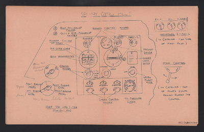
[underlined] SPERRY GYRO PILOT [/underlined]
[diagram]
[page break]
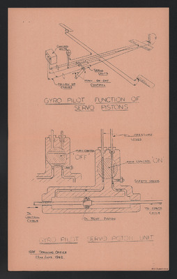
[diagram]
[underlined] GYRO PILOT [/underlined]
[underlined] FUNCTION OF SERVO PISTONS [/underlined]
[diagram]
[underlined] GYRO PILOT [/underlined]
[underlined] SERVO PISTON UNIT [/underlined]
[underlined] RAF Training Office 22nd June 1942 [/underlined]
[page break]
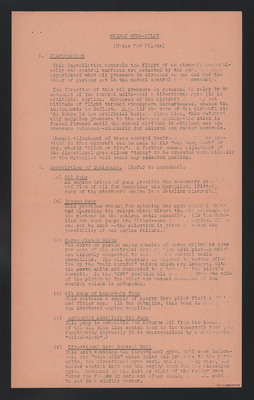
[underlined] SPERRY GYRO-PILOT [/underlined]
(Notes for Pilots)
1. [underlined] Introduction [/underlined]
This installation controls the flight of an aircraft automatically and control surfaces are actuated by the push and pull experienced when oil pressure is directed to one end and the other of pistons set in the normal control cable assembly.
The direction of this oil pressure is governed in relay by the movement of two control units--(a) a directional gyro (b) an artificial horizon. Movement of the aircraft [indecipherable words] set altitude of flight through atmosphere disturbances, causes the instruments to deflect. E.g. (if the nose of the aircraft ris[missing letters] the image in the artificial horizon rises also, this automatically supplies pressure to the elevator piston -- the stick is forced forward until the normal altitude is attained and the pressure released -- similarly for aileron and rudder controls.
Manual adjustment of these control [indecipherable word] is provided so that aircraft can be made to fly "one wing down" or say, steady "climb or dive". A further manual adjustment of the directional gyro allows "turns" to be executed automatically or the Gyropilot will steer any selected heading.
2. [underlined] Description of Equipment. [/underlined] (Refer to sketches).
(a) [underlined] Oil Pump [/underlined]
An engine driven of [sic] pump provides the necessary [indecipherable word] and flow of oil for operating the Gyropilot. (Fitted rear of the starboard engine in a Catalina aircraft.)
(b) [underlined] Vacuum Pump [/underlined]
This provides vacuum for spinning the gyro control units and operating the relays which direct the oil pressure to the pistons in the control cable assembly. (In the Catalina two such pumps are fitted -- one to [missing word] engine. [indecipherable word] one can be used -- the selection is given to cover the possibility of one engine failure.)
(c) [underlined] Servo Piston Units [/underlined]
The servo or piston units consist of three cylinders (one for each of the controls) cast en bloc with pistons which are directly connected to each of the central cable assemblies. The oil pressure is allowed to become effective by the "main control" valves which are integral with the servo units and connected to a lever in the pilot's cockpit. In the 'OFF' position oil [indecipherable words] from one side of the piston to the other and manual movement of the control column is unimpeded.
(d) [underlined] Oil Sump or Reservoir Tank [/underlined]
This contains a supply of Sperry Gyro pilot fluid a [indecipherable word] and filler cap. (In the Catalina, this tank is [indecipherable word] the Starboard engine nacelle.)
(e) [underlined] Automatic Auxiliary Oil Pump [/underlined]
This pump is automatic and returns oil from the lowest of the oil pipe line system back to the reservoir tank ([indecipherable word] functioning correctly it is characterised by a noticeable "click-clack".)
(f) [underlined] Directional Gyro Control Unit [/underlined]
This unit contains the directional gyro, ball back indicator, air "pick offs" which relay oil pressure to the servo units, the directional gyro card, the follow-up card, the rudder control knob and the caging knob for the direction gyro. Movement to the left or right of the rudder knob turns the follow up card and after caging [indecipherable words] card be set in a similar manner.
[page break]
The follow up card is directly attached to the "air pick offs" which are at neutral when the reading of the two cards co-incide. Thus, the follow-up card provides the [indecipherable word] set heading to steer, oil pressure will be applied to [indecipherable word] control until aircraft has turned about the gyro [missing word] the cards co-incide.
(g) [underlined] Bank & Climb (Artificial Horizon) Control Unit [/underlined]
This unit is normally attached to the D.I. unit and the two are spring mounted on the instrument panel mid-way between the two pilots.
This unit contains the vertical axis gyro (vacuum driven) which is used for lateral and longitudinal altitude indication and control. It also contains similar "air pick of[missing letters] with an aileron knob and an elevator knob as a manual method of setting these "pick offs" to set a control the attitude of flight. Instead of a follow up card [indecipherable word] pointe[missing letters] are provided to show the relative positions of the "pick [missing word] valves which, once again, are neutral when tabs co-incide. A caging knob is provided for [indecipherable words] horizon -- this knob is turned to the left and right for uncaging or caging the gyro.
The vacuum gauge is self explanatory and the level flight knob is discussed later.
(h) [underlined] Speed Control Valves [/underlined]
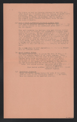
The speed valves serve to govern the rate of flow of the main oil preserve supply to the servo pistons. Three knobs are provided, are for each of the controls. When turning these knobs numbers appear in a small sector above each of them. "O" indicates the greatest restri[missing letters] is offered to the supply of oil pressure to the pistons and "6" indicates that the valves are fully open.
NOTE: Low umber setting: automatic pilot will [indecipherable word] aircraft sluggishly.
High number setting: automatic pilot will correct aircraft rapidly.
(j) [underlined] Individual Controls [/underlined]
These are master bypass valves for each of the servo pistons. E.G. if the individual rudder [indecipherable word] is "off", then the rudder can be operated manually.
[page break]
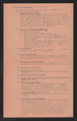
3. [underlined] Using the Gyropilot: [/underlined] – (In a Catalina)
Prior to take off the Gyro pilot must be tested and the following procedure adopted.
(a) [underlined] Check for air in Servos. [/underlined]
Before starting engines, ensure that the reservoir is [missing word] set the aeroplane controls in the central position and turn the gyro main control [underlined] ON [/underlined] (with individual controls Apply light pressure each way to each [indecipherable word]. Controls shoulb [sic] as though locked. If there is a resilient action it is an indication of air bubbles in the servo piston units. Thus air must be removed from the system before take off. Do not mistake springing of the control cable assembly for air in the servo cylinders.
(b) [underlined] Remove air from Servo Cylinders [/underlined]
1. Turn main gyro control [underlined] "OFF". [/underlined]
2. Start both engines.
3. Turn on main oil pressure valve
4. Open speed control valves to read "6".
5. With engines running at approximately 1000 rpm (or more if necessary to comply with taxying programme) on the water).
6. Work elevator, rudder and aileron, holding each control at full lock in both extreme positions for about 30 secs (or more) to allow time for [indecipherable word] air to be forced out of the end of the servo cylinders and carried back to the oil tank.
(c) [underlined] Check Vacuum [/underlined]
Should not be less than 3" of mercury at [indecipherable words] (engine speed) or more than 5" at maximum rpm.
(d) [underlined] Check oil pressure. [/underlined]
Close speed control valves when checking oil pressure with starboard engine running at 1000 rpm (or more) oil pressure should read approximately 100 lbs/square inch.
(e) [underlined] Uncage Bank and Climb Gyro. [/underlined]
If aeroplane is not level, gyro should move slowly towards correct indication of the attitude of the aircraft
(f) [underlined] Uncage Directional Gyro [/underlined]
(g) [underlined] Open Speed Control Valves. [/underlined]
A control will not operate unless its speed control is partially open.
(h) [underlined] Ensure level control is 'OFF' [/underlined]
(i) [underlined] Ensure Individual Controls are "ON" and main oil pressure supply valve is ON. [/underlined]
(j) [underlined] Set Follow-up Indices. [/underlined]
i.e. turn manual rudder control knob until both rudder cards are reading the same (Maintaining a straight taxying path). Line up aileron and [indecipherable words] tabs to co-incide by turning respective manual control knobs. NOTE: Stick and rudder controls should be held still in approximately a central position during this operat[missing letters]
(k) [underlined] Engage main gyro control slowly [/underlined]
Keeping a straight taxy path and holding manual cockpit controls.
(l) [underlined] Test Operation of Gyropilot [/underlined]
by turning Rudder, Aileron and Elevator knobs, noting that controls move both ways, in the correct direction and at approximately equal speed each way. (Up elevator will probably be slower than down elevator due to the weight of the surface.) Slow aileron or rudder one way and fast action the opposite way, or control [indecipherable words] direction only is indicative of maladjustment which [missing word] be corrected in accordance with service instructions [indecipherable word] Trouble Shooting. Set Turn Control successively [missing word] and LEFT to check operation of rudder follow-up card.
[page break]
As soon as line mechanic or pilot has become familiar with above routine he will be able to run a complete ground check [missing word] to three minutes during the run up of engines. A Gyropilot [missing words] form satisfactorily in the air, and, therefore, any malfunction of the apparatus should be corrected before any attempt is [missing words] use it.
[underlined] NOTE: BEFORE TAKE OFF MAIN CONTROL MUST BE 'OFF' [/underlined]
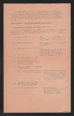
[underlined] Engaging the Gyropilot [/underlined] (in flight (not below [indecipherable word])
Several details should be checked or performed prior to engaging the Gyropilot. These are listed for convenience of the pilot. Familiarity with the Gyropilot will soon reduce this procedure to simple routine.
1. Check vacuum.
Desired vacuum is 4 inches of mercury. It should not be less than 3 inches or more than 5 [missing word]
2. Check oil pressure.
Best [indecipherable words] will have been determined [indecipherable word] original tests.
3. Open Speed Valves. to (1 or 2)
A closed speed valve locks its control in position when pilot is ON. It is, ther[missing letters] important that the valves be [missing word] prior to engaging the Gyropilot.
4. Set level control to OFF
5. Check Directional Gyro setting and be sure both gyros are uncaged.
6. Trim the airplane for "Hands Off" condition.
7. Set follow-up indices to co-incide with gyro indications.
Rudder follow up card should match Direc[missing letters] gyro [indecipherable word] index should [indecipherable word] mark at top of Bank and Climb Gyro [indecipherable words] Climb index should match mark at right end of [missing word] miniature airplane bar.
8. Set Turn Control to OFF
9. [deleted word] Ensure that individual controls are "ON".
10. Engage Gyropilot slowly.
By holding on to the [indecipherable word] as the Gyropilot is engaged the pilot can feel [indecipherable words] Gyropilot is taking [indecipherable words] functioning properly.
[diagram]
[page break]
[diagram]
[underlined] GYRO PILOT [/underlined]
[underlined] FUNCTION OF SERVO PISTONS [/underlined]
[diagram]
[underlined] GYRO PILOT [/underlined]
[underlined] SERVO PISTON UNIT [/underlined]
[underlined] RAF Training Office 22nd June 1942 [/underlined]
[page break]
[underlined] SPERRY GYRO-PILOT [/underlined]
(Notes for Pilots)
1. [underlined] Introduction [/underlined]
This installation controls the flight of an aircraft automatically and control surfaces are actuated by the push and pull experienced when oil pressure is directed to one end and the other of pistons set in the normal control cable assembly.
The direction of this oil pressure is governed in relay by the movement of two control units--(a) a directional gyro (b) an artificial horizon. Movement of the aircraft [indecipherable words] set altitude of flight through atmosphere disturbances, causes the instruments to deflect. E.g. (if the nose of the aircraft ris[missing letters] the image in the artificial horizon rises also, this automatically supplies pressure to the elevator piston -- the stick is forced forward until the normal altitude is attained and the pressure released -- similarly for aileron and rudder controls.
Manual adjustment of these control [indecipherable word] is provided so that aircraft can be made to fly "one wing down" or say, steady "climb or dive". A further manual adjustment of the directional gyro allows "turns" to be executed automatically or the Gyropilot will steer any selected heading.
2. [underlined] Description of Equipment. [/underlined] (Refer to sketches).
(a) [underlined] Oil Pump [/underlined]
An engine driven of [sic] pump provides the necessary [indecipherable word] and flow of oil for operating the Gyropilot. (Fitted rear of the starboard engine in a Catalina aircraft.)
(b) [underlined] Vacuum Pump [/underlined]
This provides vacuum for spinning the gyro control units and operating the relays which direct the oil pressure to the pistons in the control cable assembly. (In the Catalina two such pumps are fitted -- one to [missing word] engine. [indecipherable word] one can be used -- the selection is given to cover the possibility of one engine failure.)
(c) [underlined] Servo Piston Units [/underlined]
The servo or piston units consist of three cylinders (one for each of the controls) cast en bloc with pistons which are directly connected to each of the central cable assemblies. The oil pressure is allowed to become effective by the "main control" valves which are integral with the servo units and connected to a lever in the pilot's cockpit. In the 'OFF' position oil [indecipherable words] from one side of the piston to the other and manual movement of the control column is unimpeded.
(d) [underlined] Oil Sump or Reservoir Tank [/underlined]
This contains a supply of Sperry Gyro pilot fluid a [indecipherable word] and filler cap. (In the Catalina, this tank is [indecipherable word] the Starboard engine nacelle.)
(e) [underlined] Automatic Auxiliary Oil Pump [/underlined]
This pump is automatic and returns oil from the lowest of the oil pipe line system back to the reservoir tank ([indecipherable word] functioning correctly it is characterised by a noticeable "click-clack".)
(f) [underlined] Directional Gyro Control Unit [/underlined]
This unit contains the directional gyro, ball back indicator, air "pick offs" which relay oil pressure to the servo units, the directional gyro card, the follow-up card, the rudder control knob and the caging knob for the direction gyro. Movement to the left or right of the rudder knob turns the follow up card and after caging [indecipherable words] card be set in a similar manner.
[page break]
The follow up card is directly attached to the "air pick offs" which are at neutral when the reading of the two cards co-incide. Thus, the follow-up card provides the [indecipherable word] set heading to steer, oil pressure will be applied to [indecipherable word] control until aircraft has turned about the gyro [missing word] the cards co-incide.
(g) [underlined] Bank & Climb (Artificial Horizon) Control Unit [/underlined]
This unit is normally attached to the D.I. unit and the two are spring mounted on the instrument panel mid-way between the two pilots.
This unit contains the vertical axis gyro (vacuum driven) which is used for lateral and longitudinal altitude indication and control. It also contains similar "air pick of[missing letters] with an aileron knob and an elevator knob as a manual method of setting these "pick offs" to set a control the attitude of flight. Instead of a follow up card [indecipherable word] pointe[missing letters] are provided to show the relative positions of the "pick [missing word] valves which, once again, are neutral when tabs co-incide. A caging knob is provided for [indecipherable words] horizon -- this knob is turned to the left and right for uncaging or caging the gyro.
The vacuum gauge is self explanatory and the level flight knob is discussed later.
(h) [underlined] Speed Control Valves [/underlined]
The speed valves serve to govern the rate of flow of the main oil preserve supply to the servo pistons. Three knobs are provided, are for each of the controls. When turning these knobs numbers appear in a small sector above each of them. "O" indicates the greatest restri[missing letters] is offered to the supply of oil pressure to the pistons and "6" indicates that the valves are fully open.
NOTE: Low umber setting: automatic pilot will [indecipherable word] aircraft sluggishly.
High number setting: automatic pilot will correct aircraft rapidly.
(j) [underlined] Individual Controls [/underlined]
These are master bypass valves for each of the servo pistons. E.G. if the individual rudder [indecipherable word] is "off", then the rudder can be operated manually.
[page break]
3. [underlined] Using the Gyropilot: [/underlined] – (In a Catalina)
Prior to take off the Gyro pilot must be tested and the following procedure adopted.
(a) [underlined] Check for air in Servos. [/underlined]
Before starting engines, ensure that the reservoir is [missing word] set the aeroplane controls in the central position and turn the gyro main control [underlined] ON [/underlined] (with individual controls Apply light pressure each way to each [indecipherable word]. Controls shoulb [sic] as though locked. If there is a resilient action it is an indication of air bubbles in the servo piston units. Thus air must be removed from the system before take off. Do not mistake springing of the control cable assembly for air in the servo cylinders.
(b) [underlined] Remove air from Servo Cylinders [/underlined]
1. Turn main gyro control [underlined] "OFF". [/underlined]
2. Start both engines.
3. Turn on main oil pressure valve
4. Open speed control valves to read "6".
5. With engines running at approximately 1000 rpm (or more if necessary to comply with taxying programme) on the water).
6. Work elevator, rudder and aileron, holding each control at full lock in both extreme positions for about 30 secs (or more) to allow time for [indecipherable word] air to be forced out of the end of the servo cylinders and carried back to the oil tank.
(c) [underlined] Check Vacuum [/underlined]
Should not be less than 3" of mercury at [indecipherable words] (engine speed) or more than 5" at maximum rpm.
(d) [underlined] Check oil pressure. [/underlined]
Close speed control valves when checking oil pressure with starboard engine running at 1000 rpm (or more) oil pressure should read approximately 100 lbs/square inch.
(e) [underlined] Uncage Bank and Climb Gyro. [/underlined]
If aeroplane is not level, gyro should move slowly towards correct indication of the attitude of the aircraft
(f) [underlined] Uncage Directional Gyro [/underlined]
(g) [underlined] Open Speed Control Valves. [/underlined]
A control will not operate unless its speed control is partially open.
(h) [underlined] Ensure level control is 'OFF' [/underlined]
(i) [underlined] Ensure Individual Controls are "ON" and main oil pressure supply valve is ON. [/underlined]
(j) [underlined] Set Follow-up Indices. [/underlined]
i.e. turn manual rudder control knob until both rudder cards are reading the same (Maintaining a straight taxying path). Line up aileron and [indecipherable words] tabs to co-incide by turning respective manual control knobs. NOTE: Stick and rudder controls should be held still in approximately a central position during this operat[missing letters]
(k) [underlined] Engage main gyro control slowly [/underlined]
Keeping a straight taxy path and holding manual cockpit controls.
(l) [underlined] Test Operation of Gyropilot [/underlined]
by turning Rudder, Aileron and Elevator knobs, noting that controls move both ways, in the correct direction and at approximately equal speed each way. (Up elevator will probably be slower than down elevator due to the weight of the surface.) Slow aileron or rudder one way and fast action the opposite way, or control [indecipherable words] direction only is indicative of maladjustment which [missing word] be corrected in accordance with service instructions [indecipherable word] Trouble Shooting. Set Turn Control successively [missing word] and LEFT to check operation of rudder follow-up card.
[page break]
As soon as line mechanic or pilot has become familiar with above routine he will be able to run a complete ground check [missing word] to three minutes during the run up of engines. A Gyropilot [missing words] form satisfactorily in the air, and, therefore, any malfunction of the apparatus should be corrected before any attempt is [missing words] use it.
[underlined] NOTE: BEFORE TAKE OFF MAIN CONTROL MUST BE 'OFF' [/underlined]
[underlined] Engaging the Gyropilot [/underlined] (in flight (not below [indecipherable word])
Several details should be checked or performed prior to engaging the Gyropilot. These are listed for convenience of the pilot. Familiarity with the Gyropilot will soon reduce this procedure to simple routine.
1. Check vacuum.
Desired vacuum is 4 inches of mercury. It should not be less than 3 inches or more than 5 [missing word]
2. Check oil pressure.
Best [indecipherable words] will have been determined [indecipherable word] original tests.
3. Open Speed Valves. to (1 or 2)
A closed speed valve locks its control in position when pilot is ON. It is, ther[missing letters] important that the valves be [missing word] prior to engaging the Gyropilot.
4. Set level control to OFF
5. Check Directional Gyro setting and be sure both gyros are uncaged.
6. Trim the airplane for "Hands Off" condition.
7. Set follow-up indices to co-incide with gyro indications.
Rudder follow up card should match Direc[missing letters] gyro [indecipherable word] index should [indecipherable word] mark at top of Bank and Climb Gyro [indecipherable words] Climb index should match mark at right end of [missing word] miniature airplane bar.
8. Set Turn Control to OFF
9. [deleted word] Ensure that individual controls are "ON".
10. Engage Gyropilot slowly.
By holding on to the [indecipherable word] as the Gyropilot is engaged the pilot can feel [indecipherable words] Gyropilot is taking [indecipherable words] functioning properly.
Collection
Citation
Great Britain. Royal Air Force, “Sperry Gyro Pilot,” IBCC Digital Archive, accessed July 27, 2024, https://ibccdigitalarchive.lincoln.ac.uk/omeka/collections/document/34027.
Item Relations
This item has no relations.

